Melissa Parsons, Martin Thoms and Richard Norris
Cooperative Research Centre for Freshwater Ecology
University of Canberra
Monitoring River Health Initiative Technical Report Number 22
Environment Australia, 2002
ISSN 1447-1280
ISBN 0 642 54888 9
5 Instructions for the Measurement of Each Variable (continued)
Channel Cross-Sections
In a geomorphological survey, thorough description of the physical characteristics of a stream reach generally includes measurement of several cross-section profiles (Gordon et al., 1992). A channel cross-section is essentially a "slice" through the channel, made at right angles to the flow (Gordon et al., 1992). Data collected at a cross-section provides information on linear and areal channel dimensions. Aspects of channel dimension are related to discharge character and sediment transport, and can also be used to examine changes that occur in the channel profile as a result of anthropogenic or natural events. Aspects of channel dimension can also be used to calculate complex geomorphological or hydrological parameters such as Mannings n or stream power, although these are not included in the current protocol.
What amount of effort and equipment is required to measure
a cross-section?
Channel cross-sections can be measured using survey equipment, although in the current protocol, equipment is kept to a minimum (Figure 5.23) and channel cross-sections will be taken using measuring tapes. Regardless of the equipment used, the procedure for measuring cross-sections involves taking vertical measurements at several points across a horizontal transect-line. At each point, both the horizontal distance across the channel and the vertical distance to the streambed are recorded (Figure 5.24). Specific components of the cross-section will be discussed further in the next section.
In wadeable streams, cross-sections are relatively easy to measure because the entire width of the stream can be accessed, even in pools. Accessibility makes cross-sections slightly more difficult to measure in deep pools and large lowland rivers, however, there are many simple ways to sample cross-sections in these types of rivers. For example, in large rivers a boat can be used to access the width of the river or in medium sized rivers, a canoe, small boat or sometimes even a Li-Lo (air mattress) can be used to access the centre of deep pools. When weather, flow and water quality conditions are safe, cross-sections can be performed by swimming across the stream. At some sampling sites, cross-sectional measurements may also be made from a bridge. To take depth measurements along a horizontal transect, a marked pole (e.g. a metre ruler, survey staff or custom made device) can be used, or in slow flowing areas a weighted tape measure or weighted and marked rope is also suitable. Another method that has been used successfully in the River Habitat Audit Procedure (Anderson, 1993a) is to rig a depth sounder onto a rubber flotation board, that can be pushed, pulled or placed across the river to take depth measurements at the required intervals.
It is important that the required numbers of cross-sections are measured
at every sampling site. Thus, preparation for a field trip should include planning
of the logistics and equipment required to make cross-sectional measurements
at all sampling sites, even those located on large or deep rivers. Health
and safety issues must be taken into consideration when planning cross-section
sampling in any type of river.
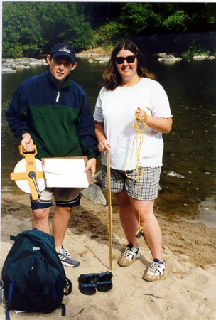
Figure 5.23 Equipment required for measuring cross-sections in a wadeable stream. Note that the metre ruler and weighted rope are interchangeable, depending on stream depth. Waders are not shown because wading shoes were used at this site. Additionally, this photo represents the equipment that needs to be carried to assess the whole of a wadeable sampling site, once water quality measurements have been taken.
The components that must be measured at each cross-section are detailed in Figure 5.24 and are described as follows:
Stream width at the water surface is the width of the water surface
at the time of sampling.
Baseflow stream width is the width of the stream at a point corresponding
to baseflow conditions. The baseflow water mark is evidenced by the limit of
terrestrial vegetation, eroded area or a break in bank sediment. Under baseflow
conditions, baseflow stream width will be equivalent to stream width at the
water surface.
Bankfull channel width is the width of the channel between the top of
the banks. Bankfull level is the point at the top of the channel where under
high flow conditions, the water level would be even with the top of the banks,
or in a floodplain river, at the point just before water would spill over onto
the floodplain. Further information on the identification of bankfull level
is provided in Figure 5.31.
Bank height is the height of the bank measured from the baseflow water
mark to the top of the banks. Bank height is measured at both the left and right
banks.
Bank width is the width of the bank, extending from the edge of the
stream (at the watermark) to the bankfull point. Bank width is measured at both
the left and right banks.
Vertical distance between water surface and baseflow water mark is the
height difference between the water surface and the baseflow water mark. Vertical
distance between water surface and baseflow water mark is measured to compensate
for conditions where flow is below normal levels at the time of sampling. This
component is measured at both the left and right banks.
Vertical water depths and horizontal distances are measured together
at several points across the width of the stream. At each horizontal distance
from the edge of the stream, water depth is recorded.
Each of these components are used in various combinations to calculate cross-sectional variables (see section titled 'What variables are derived from a cross-section?') and thus, it is vital to make all of these measurements at each cross-section.
Figure 5.24 Components of a channel cross-section. A tape measure is stretched across the surface of the water and the vertical water depth and horizontal distance from the bank are both measured at several points across the entire channel width. Bank height and the distance between the water surface and the water mark are measured on the left and right sides of the channel. Refer to text for more information.
The field procedure for measuring a cross-section is as follows:
- At the point where the cross-section is to be located, identify the bankfull level, baseflow water mark level and the present water level. Decide whether the flow level is roughly equal to baseflow condition and thus, whether the stream width at the watermark is the same as the stream width at the present water surface. Further information on the identification of bankfull level is given in the section titled 'How are the bankfull and baseflow water mark levels identified in different channel types?'
- Stretch a tape measure across the surface of the water from one edge of
the stream to the other and secure both ends. Record the stream width at
the water surface (Figure 5.25).
- With the tape measure still in place move back across the stream and record
the vertical water depth at a minimum of 5 and a suggested maximum
of 15 points across the tape measure, using the metre ruler or weighted rope,
or similar (Figure 5.26). The number of points measured will depend on the
width and heterogeneity of the channel and in large streams, more than 15
points may be required to characterise the streambed profile. Points do not
have to be regularly spaced, but where possible, should represent breaks in
the streambed profile. Be sure to record the horizontal distance across
the tape measure for each depth measurement because these distances are critical
to the calculation of cross-sectional dimensions.
- Move back across the stream and measure bank height and bank width.
Bank height is usually measured with a metre ruler (Figure 5.27) but for wide
banks, a tape measure can be used to aid identification of bank height (Figure
5.27). Bank width can be measured with a tape measure (Figure 5.27) or estimated
when access is difficult. Where necessary, also measure vertical distance
between the water surface and the baseflow water mark. In situations where
the water level at the time of sampling is equal to the baseflow water mark,
the vertical distance between the water surface and the baseflow water mark
will be zero.
- With one person at either side of the stream, measure stream width at
the water mark using the tape measure. In situations where the water level
at the time of sampling is equal to the baseflow water mark, the stream width
at the baseflow water mark will be the same as the stream width at the water
surface.
- Return to the starting bank and measure bank height, bank width
(Figure 5.27) and where necessary, vertical distance between the water
surface and the water mark. In situations where the water level at the
time of sampling is equal to the water mark, the vertical distance between
the water surface and the water mark will again be zero.
- Sketch the cross-sectional channel shape, including the location of bars or braids, and indicate where the bankfull and baseflow water mark levels were located.
- In situations where it is difficult to stretch a tape measure across the stream, lateral thinking can be applied to take the cross-section. For example, in a wide wadeable stream with difficult access across the channel, horizontal distances can be estimated by pacing or by using a small 5m rope and vertical depths can be taken with a weighted rope (Figure 5.28). In a small deep stream, the weighted rope can be tied to the end of a survey staff or similar and held out over the water to take horizontal distance and vertical depth measurements (Figure 5.28).
In summary, a cross-section requires measurement of the following components:
- stream width measured at the baseflow water mark level
- stream width measured at the water level at the time of sampling
- bank height for both banks
- bank width for both banks
- vertical distance between the water mark level and the water level at the time of sampling, for both banks
- between 5 and 15 water depth measurements taken at recorded intervals across the stream
- channel width measured at bankfull level, which is a function of stream width at the water mark and left and right bank widths (see data sheet)
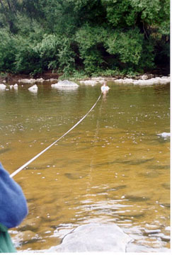
Figure 5.25 Stretching the tape measure across the stream at the start
of a cross-section.
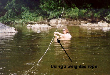
Figure 5.26(a) Measurement of vertical water depths across at a cross-section in a wadeable stream, using a weighted rope or metre ruler.
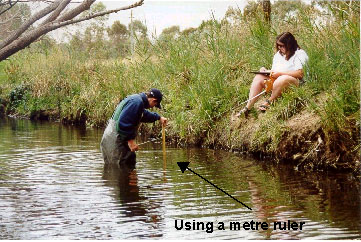
Figure 5.26(b) Measurement of vertical water depths across at a cross-section in a wadeable stream, using a weighted rope or metre ruler.
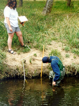
Figure 5.27 (a) Measurement of bank height using a metre ruler or metre ruler and tape measure on a wide bank. In the photo on the right, bank width can also be measured with the tape measure.
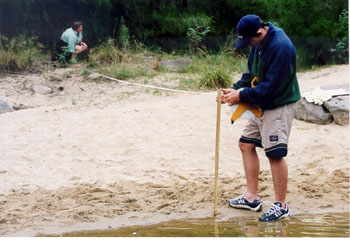
Figure 5.27 (b) Measurement of bank height using a metre ruler or metre ruler and tape measure on a wide bank. In the photo on the right, bank width can also be measured with the tape measure.
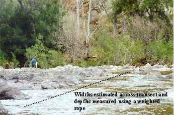
Figure 5.28 (a) Measurement of cross-sections in some difficult wadeable streams. In the top photo the bed was bedrock based and difficult to walk across with the tape measure, so horizontal distances were estimated and depths were measured with a weighted rope. In the bottom photo, the small urban stream was deep and dirty so a survey staff was used to take horizontal distances. Vertical depths were taken using an attached weighted rope.
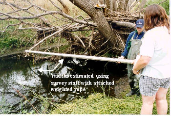
Figure 5.28 (b) Measurement of cross-sections in some difficult wadeable streams. In the top photo the bed was bedrock based and difficult to walk across with the tape measure, so horizontal distances were estimated and depths were measured with a weighted rope. In the bottom photo, the small urban stream was deep and dirty so a survey staff was used to take horizontal distances. Vertical depths were taken using an attached weighted rope.
How many cross-sections are needed at each sampling site,
and where are they placed?
The number and placement of cross-sections at each sampling site is dependent on the relative heterogeneity of the channel.
Homogeneous sampling sites
Two cross-sections should be measured at sampling sites that have a relatively uniform channel shape and sediment composition (Figure 5.29). These types of sampling sites generally correspond to large, low gradient rivers without riffles. The two cross-sections should be placed close to the upstream and downstream boundaries of the sampling site. These cross-sections should not be located on the apex of a bend.
Figure 5.29 Example placement of cross-sections at a homogeneous sampling site.
Crosses indicate the apex of bends, where cross-sections should not be placed.
Heterogeneous sampling sites
Three cross-sections should be measured at sampling sites that have a relatively complex channel shape and sediment composition (Figure 5.30). These types of sampling sites generally correspond to small to medium wadeable rivers with a cascade or riffle-pool flow character. The three cross-sections should be placed to represent the different types of bedform units present at the sampling site (ie. riffles, pools, runs) and must include at least one pool. In most streams, appropriate placement of cross-sections would include one riffle, one run and one pool, spread throughout the entire length of the sampling site. Again, cross-sections should not be placed on the apex of a bend.
Figure 5.30 Example placement of cross-sections at a heterogeneous sampling site. Crosses indicate the apex of a bend where cross-sections should not be placed.
Accurate identification of the bankfull channel and baseflow water mark levels is fundamental to the measurement of cross-sections. The placement of bankfull and watermark levels at cross-sections located in different channel types is explained in Figure 5.31.
Bankfull channel level is the point within the stream channel where the water level would fill the channel to the tops of the banks. The 'tops of the banks' varies according to channel type (Figure 5.31).
The baseflow water mark level is generally evidenced by the limits of terrestrial
vegetation, scour lines, growth of macrophytes or abrupt changes in bank slope
(Figure 5.24). However, the baseflow water mark level can be difficult to identify
in some situations, using the above criteria. An additional method that can
be used to aid the identification of the baseflow water mark level is residual
pool depth (Lisle, 1987). Residual pool depth is the difference in depth or
bed elevation between a pool and the downstream riffle crest. Residual pool
depth is measured by surveying a pool with a tape measure and ruler and subtracting
the depth of the riffle crest from those in the pool. A detailed description
of the residual pool depth method is available to down load from the United
States Forest Service website at http://www.rsl.psw.fs.fed.us/projects/water/Lisle87.pdf
 |
Confined upland
Confined channels have no floodplain development and are generally found in upland areas with steep valleys. Under undisturbed conditions, bankfull width is usually not much larger than baseflow width. The bankfull level in a confined channel is evidenced by the limit of terrestrial vegetation, the growth of macrophytes, the presence of moss or lichen, the presence of scour marks or an abrupt change in bank slope. (Figure 5pt31 - 1 of 6)
|
 |
Channelised
This type of stream is found where islands (i.e. bars) have formed within the channel. The bars may be vegetated or unvegetated. The placement of a cross-section should run across the bars. Bankfull width should include the bar portion, but baseflow width should break around the bar portion. (Figure 5pt31 - 1 of 6)
|
 |
Channel with instream bars
This type of stream occurs where bars have formed and are attached to the banks. The placement of a cross-section should run across the bars. Bankfull width should include the bar portion, but baseflow width should not include the bar portion if it is not within the baseflow area. (Figure 5pt31 - 1 of 6)
|
 |
Terraced channel
Terraced channels are channels in which the banks are characterised by bench formations. Terraced channels generally occur in lowland floodplain rivers. Regardless of the number of benches present, bankfull width is always measured to the top of the first bench only. (Figure 5pt31 - 1 of 6)
|
 |
One bank higher than the other
When one bank is higher than the other, bankfull width is measured to the top of the lowest bank. This is because the top of the lowest bank represents the point where water would overtop the bank and spill onto the floodplain. (Figure 5pt31 - 1 of 6)
|
 |
Braided channels
Braided channels contain multiple channels that diverge and converge around many islands. Banks may be poorly defined in these types of channels, although the lateral limit of the channel can often be identified. Cross-sectional bankfull width and baseflow width of should be measured across all the threads of a braided channel. (Figure 5pt31 - 1 of 6)
|
Figure 5.31. Identification of bankfull level in different channel types. Baseflow
water mark level is also drawn on for context, however, the actual position
of the water mark level relative to the bankfull level can only be determined
after examination in the field.
The variables derived from data collected at the cross-sections are given in Table 5.4. Several of these variables are derived directly from field cross-section measurements, several are derived following office-based adjustments and several are derived using the AQUAPAK1 computer package. Instructions for the calculation of each variable are provided in the following pages.
Table 5.4 Variables derived from cross-section data
| Variable |
Derivation |
| Bankfull channel width |
Calculated directly from the cross-section data collected in the field |
| Bankfull channel depth |
Cross-section data collected in the field is adjusted in the office |
| Baseflow stream width |
Taken directly from the cross-section data collected in the field |
| Baseflow stream depth |
Cross-section data collected in the field is adjusted in the office |
| Bank width |
Calculated directly from the cross-section data collected in the field |
| Bank height |
Calculated directly from the cross-section data collected in the field |
| Bankfull width:depth ratio |
Calculated using the bankfull channel width and bankfull channel depth
variables |
| Bankfull cross-sectional area2 |
Calculated in AQUAPAK using adjusted cross-section data |
| Bankfull wetted perimeter2 |
Calculated in AQUAPAK using adjusted cross-section data |
| Baseflow cross-sectional area2 |
Calculated in AQUAPAK using adjusted cross-section data |
| Baseflow wetted perimeter2 |
Calculated in AQUAPAK using adjusted cross-section data |
In addition to these variables, substrate composition, bank material, riparian
zone width, filamentous algae cover, periphyton cover, moss cover and detritus
cover will also be measured in the immediate vicinity of the cross-section.
Further information on these variables are provided on each instruction sheet.