Melissa Parsons, Martin Thoms and Richard Norris
Cooperative Research Centre for Freshwater Ecology
University of Canberra
Monitoring River Health Initiative Technical Report Number 22
Environment Australia, 2002
ISSN 1447-1280
ISBN 0 642 54888 9
| VARIABLE NAME | Alkalinity |
| CATEGORY | Water chemistry |
| CONTROL OR RESPONSE | Control |
| OFFICE OR FIELD | Field |
| UNITS OF MEASUREMENT | mg CaCO3 l-1 |
| INDICATES | Buffering capacity of water, which in turn is related to catchment geology. |
Alkalinity should be determined in the field by acid titration. Alternatively, a water sample may be taken and kept on ice in the field, before determination of alkalinity immediately upon return to the laboratory.
Standard method (A.P.H.A., 1992)
Collect a water sample from one point in the centre of the stream. Place 100ml of river water in a clean beaker with two drops of Methol Red indicator. While swirling the water in the beaker, use a syringe to add Sulfuric Acid (H2SO4, 0.02N), drop by drop, until the colour of the water just turns and remains pink (Figure 5.3). Record the amount of acid used in the titration. Alkalinity (as mg CaCO3 l-1) is calculated as:
![]()
where:
A = ml H2SO4
N = normality of acid (0.02N)
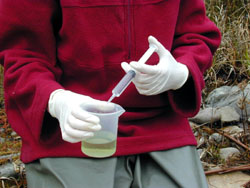
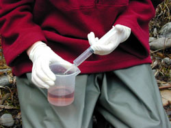
Figure 5.3 Field alkalinity titration. Before addition of acid, the water is green (left) and upon titration endpoint, the water is pink (right).
| VARIABLE NAME | Total stream length |
| CATEGORY | Catchment characteristics |
| CONTROL OR RESPONSE | Control |
| OFFICE OR FIELD | Office |
| UNITS OF MEASUREMENT | km |
| INDICATES | Travel time of water through the drainage network and availability of sediment for transport. |
Total stream length is calculated by measuring the length of all perennial streams within the catchment area upstream of each sampling site. Total stream length is measured off 1:100 000 topographic maps.
Total stream length is also used to calculate the drainage density and mean stream slope variables.
| VARIABLE NAME | Drainage density |
| CATEGORY | Catchment characteristics |
| CONTROL OR RESPONSE | Control |
| OFFICE OR FIELD | Office |
| UNITS OF MEASUREMENT | km |
| INDICATES | The balance between erosive forces and the resistance of the ground surface. Drainage density is also related to climate, geology, soils and vegetation cover in the catchment. |
Drainage density (RD) is calculated within the catchment area upstream of each sampling site by dividing the total stream length for the catchment (see total stream length variable) by the catchment area (see catchment area upstream of the site variable):
where:
∑
L = total stream length
A = catchment area upstream of the sampling site
Total stream length should be measured in km and catchment area upstream of the sampling site in km2
The overall unit of measurement for drainage density is km.
| VARIABLE NAME | Catchment area upstream of the site |
| CATEGORY | Catchment characteristics |
| CONTROL OR RESPONSE | Control |
| OFFICE OR FIELD | Office |
| UNITS OF MEASUREMENT | km2 |
| INDICATES | Relative water yield and the number and size of streams in the catchment. |
The catchment area upstream of a site is defined as the total area of catchment that drains into the sampling site (Figure 5.4).
Catchment area upstream of each sampling site is measured off 1: 100 000 scale topographic maps using a planimeter. The boundaries of each catchment are identified by examination of topographic contours.
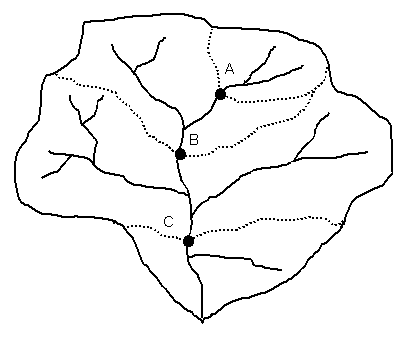
Figure 5.4 Example calculation of catchment area upstream of the sampling site. Catchment areas for successive sites within a catchment are additive. The catchment area of the most upstream site, site A, is calculated first. Then, the catchment area upstream of site B includes the area of site A and B, and the catchment area upstream of site C includes the area of sites A and B and C.
| VARIABLE NAME | Elongation ratio |
| CATEGORY | Catchment characteristics |
| CONTROL OR RESPONSE | Control |
| OFFICE OR FIELD | Office |
| UNITS OF MEASUREMENT | Dimensionless |
| INDICATES | Catchment shape. |
Elongation ratio (Re) is calculated for the catchment upstream of each sampling site by dividing the diameter of a circle with the same area as the catchment, by the length of the catchment:
where:
Dc = the diameter of a circle with the same area as the catchment
area upstream of the sampling site1
L = the maximum length of the catchment along a line basically parallel
to the main stem
1The formula for calculation of the diameter of a circle with a
certain area is: √ [(4 x area) / π ]
An example calculation for a catchment with an area of 740km2 is:
√[(4 x 740) / π ] = 30.7km
After Gordon et al. (1992)
| VARIABLE NAME | Relief ratio |
| CATEGORY | Catchment characteristics |
| CONTROL OR RESPONSE | Control |
| OFFICE OR FIELD | Office |
| UNITS OF MEASUREMENT | Dimensionless |
| INDICATES | The intensity of erosion processes on slopes which in turn, influences sediment supply and the ability of the river to transport sediment. |
Relief ratio (Rr) is calculated for the catchment upstream of each sampling site by dividing the difference in elevation between the highest point in the drainage divide and the sampling site by the length of the catchment:
where:
h = the difference in elevation between the highest point on the drainage divide and the sampling site
L = the maximum length of the catchment along a line approximately parallel to the main stem
The units of h and L should be equal (ie. metres or kilometres) so as to make Rr dimensionless (Gordon et al., 1992).