Melissa Parsons, Martin Thoms and Richard Norris
Cooperative Research Centre for Freshwater Ecology
University of Canberra
Monitoring River Health Initiative Technical Report Number 22
Environment Australia, 2002
ISSN 1447-1280
ISBN 0 642 54888 9
River characterisation requires the ordering of sets of observations or characteristics into meaningful groups based on their similarities or differences (Naiman et al., 1992; Wadeson and Rowntree, 1994). Implicit in this exercise is the assumption that relatively distinct boundaries exist and that these may be identified by a discrete set of variables. Although river systems are continuously evolving and often display complexity, the grouping of a set of elements with a definable structure can aid in examining the physical structure of river systems. It may also assist in understanding why rivers have certain biological characteristics.
Geomorphological analyses of river systems often reveal a continuum of functions that change in an upstream-downstream direction. For example, headwater regions often provide a net supply of water and sediment to the river network, while through deposition, lowland alluvial river channels store sediment in vast floodplains. Changes in the flow and sediment regime throughout a catchment will be manifested by changes in river morphology and behaviour. Schumm (1988) suggests that there are three broad functional zones within a catchment:
The geomorphological processes conveyed through these functional river zones will be incorporated into the reference site selection procedure and together with the climatic and geological regions, will form the basis for stratification of sampling sites across the landscape.
Figure 2.2 Broad functional zone types within a river system. After Schumm (1988).
For the purposes of the physical assessment protocol, functional zones are defined as lengths of river that have similar water and sediment discharge regimes. Four zone types are recommended in the reference site selection procedure: upper zone A (low energy unconfined), upper zone B (high energy confined), transition zone and lower zone. Water and sediment discharge regimes manifest distinctive geomorphological characteristics in each of these zone types and thus, rivers can be divided into zones using three key indicators of channel character: channel slope, valley character and river channel or planform pattern. This section describes the four functional zone types, and the method used to divide rivers into these zones.
Reference sites will be stratified across four functional zone types. These zone types represent a broad continuum of geomorphological processes occurring within a catchment and thus, will be applicable and valid in the majority of river systems found in Australia. Each zone type will be described in more detail in the following pages.
Upper zone A (low energy unconfined)
Upper zone A is characterised by long pools that are separated by short channel constrictions (ie. chain of ponds morphology). The pools form upstream of the channel constrictions, and are the dominant morphological feature in this zone type (Figure 2.3). Channel constrictions are generally associated with major bedrock bars that extend across the channel, or substantial localised gravel deposits that act as riffle areas. Local riverbed slopes increase significantly at these constrictions, representing small areas of relatively high energy that contrast with the relatively low bed slopes and energies of the pool environment. Overall, bed slope in upper zone A is in the order of 0.0001, with a corresponding stream power in the order of 1.5 W/m2. Stream power (ω) is related to the rate at which 'work' (sediment movement) is done or at which energy is expended in a stream or river.
The planform channel configuration of upper zone A is controlled by the valley morphology. Generally, the river channel has a small flanking floodplain (up to 30m) because of the narrow valley floor configuration. Hence, valley conditions limit floodplain development. Bankfull channel dimensions can be up to 30m in width, 3-4 metres in depth/height and may have a width to depth ratio of up to 10. Bankfull channel capacities do not generally exceed 30 m3 s-1.
The nature of channel sediment or substratum in upper zone A consists of fine silt/clay material overlying a bedrock/cobble base in the pools. However, gravel/cobble or bedrock substrates dominate the short constricted riffle areas. Bankfull flows have the competence to entrain the finer bed substratum, however, discharges in excess of 50 m3 s-1 are required to initiate motion of the coarser material. Thus, the riverbed in this zone type is relatively stable because discharges large enough to move coarse materials rarely occur.
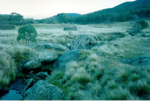
Figure 2.3: Typical example of an upper low energy unconfined zone.
Upper zone B (high energy confined)
Upper zone B is a high energy zone dominated by bed slopes greater than 0.002 and often by steep bed slopes greater than 0.010. Bankfull stream power is generally in excess of 250 W/m2 and can exceed 400 W/m2 in steeper sections. Bedrock chutes, large boulder/cobble/gravel accumulations and scour pools dominate in the channel. Bed sediments are relatively immobile because the streambed tends to be armoured (ie. the coarse surface layer sediments shield the finer sediments beneath it). However, cobble and gravel accumulations are highly mobile during flood flows. The lack of any major sedimentary deposits, together with the high energy environment, suggests that upper zone B is an important source of sediment for the downstream river system (Figure 2.4).
Planform channel pattern in upper zone B is confined and controlled by valley morphology, and the river channel generally exhibits an irregularly meandering pattern that is superimposed on a larger valley pattern. Hence, channels in this zone have limited floodplain development. In highly confined sections, the floodplain will be absent and sediments will be added directly to the channel from adjacent valley side slopes. However, in less confined sections, small floodplain formations may be present and are characterised by a series of floodplains of different ages, inset into higher level terraces.
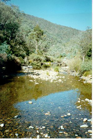
Figure 2.4 Typical example of an upper high energy confined zone.
Transition zone
The transition zone is characterised by mobile bed sediments, large sediment storage areas within the channel and an active channel (Figure 2.5). The presence of well developed inset floodplain features such as benches, point bars, cutoffs and levees signify the relatively active and unrestricted nature of this river-floodplain environment. Valley floor widths of up to 10km enable floodplain development and stream migration.
In the transition zone, the river channel is freely meandering with an irregular planform pattern. Sinuosity is generally between 1.7 and 1.95, and stream power generally ranges from 8 to 20 W/m2. Meander wavelengths are generally less than 2km.
The morphology of the channel environment is extremely variable with bars (point and lateral), benches (at various levels) and riffle/pool sequences present alone or in combination. These in-channel storage features reflect high rates of sediment transport. Riverbed sediments typically have a bimodal distribution (median grain size of 64 to 100mm) and the bed is usually highly mobile.
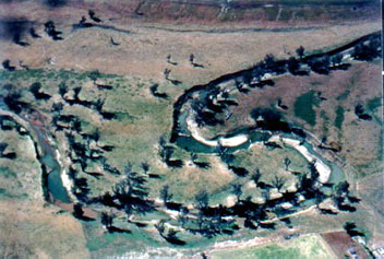
Figure 2.5 Typical example of a transition zone.
Lower zone
A distinguishing feature of the lower zone is the significant increase in the width of the valley floor (>15km) and associated floodplain surface (Figure 2.6). There are strong and active links between the river and the floodplain, and the lower zone may contain well developed features such as distributary or flood channels (channels that carry water onto the floodplain), former or paleo channels, avulsions, cut-offs or anabranches (channels that dissect the floodplain and rejoin the main channel). The channel displays a typically unrestricted meandering style, with a relatively high sinuosity of about 1.8 to greater than 2.3. Meander wavelengths are approximately 200-700m.
The appreciable fining of bed sediment is a clear distinguishing feature between the transition zone and the lower zone. Bed sediments in the lower zone are typically composed of fine materials such as sand, silt and clay. The bank sediments are also composed of fine materials. As a result, stream banks are often steep in the lower zone and may be naturally susceptible to erosion. The bankfull channel has widths that range between about 30-100m and bankfull depths that range between 3 and 15 metres.
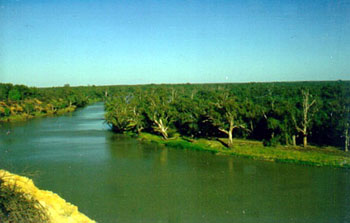
Figure 2.6 Typical examples of a lower zone (1 of 4 photos).
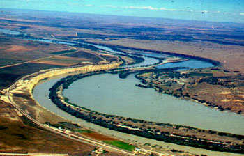
Figure 2.6 Typical examples of a lower zone (2 of 4 photos).
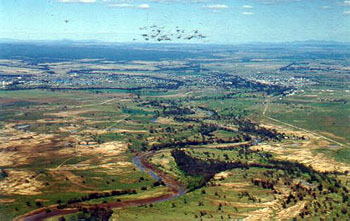
Figure 2.6 Typical examples of a lower zone (3 of 4 photos).
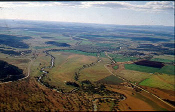
Figure 2.6 Typical examples of a lower zone (4 of 4 photos).
Functional zone types are identified by drawing up long profiles of slope, valley width and planform channel pattern (Figure 2.7). A long profile is a plot of the character of interest against downstream river distance. Long profiles are constructed for EACH river within EACH region, using topographic maps.
The completed long profiles for each river are examined simultaneously to identify the presence of one or more functional zone types (Figure 2.8), according to the characteristics described in Section 2.4.2.1. Supplementary information such as aerial photographs, satellite images, sediment data or local knowledge can also be used to confirm the interpretations of functional zone types from the long profiles. Once identified from the long profiles, the zone types that occur along each river are marked onto topographic maps.

There can be a high level of variability and complexity in the arrangement of functional zone types. The four zone types are broadly sequential along the river continuum, however, the same zone type may be identified more than once in the same river (Figure 2.8). Additionally, it is common for rivers to contain only one or two functional zone types. It is recommended that the division of rivers into functional zone types should proceed according to the above instructions, but in consultation with a geomorphologist.
| Long profile | Method | Example profile |
|---|---|---|
| SLOPE | Plot altitude against distance downstream. Altitude (m) and distance from source (km) can be measured off topographic maps. | 
|
| VALLEY CHARACTER | Plot valley width against distance downstream. Valley width is the distance (m) between the first topographic contours, on either side of the channel. Valley width should be measured off the lowest map scale possible. |  |
| PLANFORM CHANNEL PATTERN | Determine the channel patterns that occur along the length of each river, according to the following categories:  |
 |
Figure 2.7 Construction of long profiles for slope, valley width and planform channel pattern. Assessments of each variable are made using topographic maps. Measurements should be taken at regular intervals along the river, according to size and variability. For example, in a 60km long river, measurements should be made every 5km but in a 250km long river, measurements should be made every 10km.
| Slope
|
Breaks in slope, valley width and planform channel pattern are marked on the long profiles. Then, these breaks are assigned to functional zone types, according to the descriptions given in Section 2.4.2.1 and any supplementary information that is available (see Section 2.4.2.3). |
| Valley width
|
The final sequence of functional zone types for this example is UZA – UZB – UZA – TZ – LZ. |
 |
The start and endpoints of these functional zones should then be marked on topographic maps. |
Figure 2.8 (see next below) Interpretation of functional zone types from long profiles. For the zone types, UZA = Upper Zone A, UZB = Upper Zone B, TZ = transition zone and LZ = lower zone. More information on zone types is provided in Section 2.4.2.1.